1/5

GB151 / ASME / PED / JIS / Oct/ DIN Standards Steel Pressure Vessel Tanks Chemical Tanks Storage
$100.00 / Piece
- FOB Price:
- Negotiable | Get Latest Price
- Order Quantity:
- 1 Set / Sets
- Supply Ability:
- 1000 Set / Sets per Month
- Port:
- shanghai
- Payment Terms:
- T/T L/C D/P D/A Credit Card PayPal Cash Escrow Other
- Delivery Detail:
- 5 days
Hot in store


Product Details
Product Name: GB151 / ASME / PED / JIS / Oct/ DIN Standards Steel Pressure Vessel, Tanks, Chemical Tanks, Storage Tanks, Flash Tank, Expansion Vessel, Heat Exchanger 2 Model NO.: pressure vessel Condition: New Pressure Level: 0 ~10 MPa Storage Medium: Optional Pressure: 0 ~ 10 MPa Material: Carbon Steel Application: Liquid Function: Storage Pressure Vessel Oper. Years: 10 ~25 Years Trademark: JIANENG Transport Package: Wooden Box or Optional Specification: optional Origin: China HS Code: 8479899990 Product Description PRESSURISED DEAERATORSThe need to remove gases from boiler feedwater and the operation of a pressurised deaerator, plus calculations.Why gases need to be removed from boiler feedwater?Oxygen is the main cause of corrosion in hotwell tanks, feedlines, feedpumps and boilers. If carbon dioxide is also present then the pH will be low, the water will tend to be acidic, and the rate of corrosion will be increased. Typically the corrosion is of the pitting type where, although the metal loss may not be great, deep penetration and perforation can occur in a short period.Elimination of the dissolved oxygen may be achieved by chemical or physical methods, but more usually by a combination of both.The essential requirements to reduce corrosion are to maintain the feedwater at a pH of not less than 8.5 to 9, the lowest level at which carbon dioxide is absent, and to remove all traces of oxygen. The return of condensate from the plant will have a significant impact on boiler feedwater treatment - condensate is hot and already chemically treated, consequently as more condensate is returned, less feedwater treatment is required.Water exposed to air can become saturated with oxygen, and the concentration will vary with temperature: the higher the temperature, the lower the oxygen content.The first step in feedwater treatment is to heat the water to drive off the oxygen. Typically a boiler feedtank should be operated at 85°C to 90°C. This leaves an oxygen content of around 2 mg/litre (ppm). Operation at higher temperatures than this at atmospheric pressure can be difficult due to the close proximity of saturation temperature and the probability of cavitation in the feedpump, unless the feedtank is installed at a very high level above the boiler feedpump.The addition of an oxygen scavenging chemical (sodium sulphite, hydrazine or tannin) will remove the remaining oxygen and prevent corrosion.This is the normal treatment for industrial boiler plant in the UK. However, plants exist which, due to their size, special application or local standards, will need to either reduce or increase the amount of chemicals used. For plants that need to reduce the amount of chemical treatment, it is common practice to use a pressuriseddeaerator.Operating principles of a pressurised deaeratorIf a liquid is at its saturation temperature, the solubility of a gas in it is zero, although the liquid must be strongly agitated or boiled to ensure it is completely deaerated.This is achieved in the head section of a deaerator by breaking the water into as many small drops as possible, and surrounding these drops with an atmosphere of steam. This gives a high surface area to mass ratio and allows rapid heat transfer from the steam to the water, which quickly attains steam saturation temperature. This releases the dissolved gases, which are then carried with the excess steam to be vented to atmosphere. (This mixture of gases and steam is at a lower than saturation temperature and the vent will operate thermostatically). The deaerated water then falls to the storage section of the vessel.A blanket of steam is maintained above the stored water to ensure that gases are notre-absorbed.Water distributionThe incoming water must be broken down into small drops to maximise the water surface area to mass ratio. This is essential to raising the water temperature, and releasing the gases during the very short residence period in the deaerator dome (or head).Breaking the water up into small drops can be achieved using one of the methods employed inside the dome's steamenvironment.There are of course advantages and disadvantages associated with each type of water distribution, plus cost implications. Table 3.21.1 compares and summarises some of the most importantfactors:Control systemsWatercontrolA modulating control valve is used to maintain the water level in the storage section of the vessel. Modulating control is required to give stable operating conditions, as the sudden inrush of relatively cool water with an on/off control water control system could have a profound impact on the pressure control, also the ability of the deaerator to respond quickly to changes indemand.Since modulating control is required, a capacitance type level probe can provide the required analogue signal of waterlevel.SteamcontrolA modulating control valve regulates the steam supply. This valve is modulated via a pressure controller to maintain a pressure within the vessel. Accurate pressure control is very important since it is the basis for the temperature control in the deaerator, therefore a fast acting, pneumatically actuated control valve will be used. Note: A pilot operated pressure control valve may be used on smaller applications, and a self-acting diaphragm actuated control valve may be used when the load is guaranteed to be fairlyconstant.The steam injection may occur at the base of the head, and flow in the opposite direction to the water (counter flow), or from the sides, crossing the water flow (cross flow). Whichever direction the steam comes from, the objective is to provide maximum agitation and contact between the steam and water flows to raise the water to the requiredtemperature.The steam is injected via a diffuser to provide good distribution of steam within the deaeratordome.The incoming steam alsoprovides:A means of transporting the gases to the air vent.A blanket of steam required above the stored deaerated water.Deaerator air ventingcapacityIn previous Modules, typical feedwater temperatures have been quoted at around 85°C, which is a practical maximum value for a vented boiler feedtank operating at atmospheric pressure. It is also known that water at 85°C contains around 3.5 grams of oxygen per 1 000 kg of water, and that it is the oxygen that causes the major damage in steam systems for two main reasons. First, it attaches itself to the inside of pipes and apparatus, forming oxides, rust, and scale; second, it combines with carbon dioxide to produce carbonic acid, which has a natural affinity to generally corrode metal and dissolve iron. Because of this, it is useful to remove oxygen from boiler feedwater before it enters the boiler. Low-pressure and medium-pressure plant supplied with saturated steam from a shell type boiler will operate quite happily with a carefully designed feedtank incorporating an atmospheric deaerator (referred to as a semi-deaerator). Any remaining traces of oxygen are removed by chemical means, and this is usually economic for this type of steam plant. However, for high-pressure water-tube boilers and steam plant handling superheated steam, it is vital that the oxygen level in the boiler water is kept much lower (typically less than seven parts per billion - 7 ppb), because the rate of attack due to dissolved gases increases rapidly with higher temperatures. To achieve such low oxygen levels, pressurised deaerators can be used.If feedwater were heated to the saturation temperature of 100°C in an atmospheric feedtank, the amount of oxygen held in the water would theoretically be zero; although in practice, it is likely that small amounts of oxygen will remain. It is also the case that the loss of steam from a vented feedtank would be quite high and economically unacceptable, and this is the main reason why pressurised deaerators are preferred for higher pressure plant operating typically above 20 bar g.A pressurised deaerator is often designed to operate at 0.2 bar g, equivalent to a saturation temperature of 105°C, and, although a certain amount of steam will still be lost to atmosphere via a throttled vent, the loss will be far less than that from a vented feedtank.It is not just oxygen that needs to be vented; other non-condensable gases will be rejected at the same time. The deaerator will therefore vent other constituents of air, predominantly nitrogen, along with a certain amount of steam. It therefore follows that the rejection rate of air from the water has to be somewhat higher than 3.5 grams of oxygen per 1 000 kg of water. In fact, the amount air in water at 80°C under atmospheric conditions is 5.9 grams per 1 000 kg of water. Therefore, a rejection of 5.9 grams of air per 1 000 kg of water is needed to ensure that the required amount of 3.5 grams of oxygen is being released. As this air mixes with the steam in the space above the water surface, the only way it can be rejected from the deaerator is by the simultaneous release of steam.The amount of steam/air mixture that needs to be released can be estimated by considering the effects of Dalton's Law of partial pressures and Henry's Law.Consider the feasibility of installing a deaerator. Prior to installation, the boiler plant is fed by feedwater from a vented feedtank operating at 80°C. This essentially means that each 1 000 kg of feedwater contains 5.9 gram of air. The proposed deaerator will operate at a pressure of 0.2 bar g, which corresponds to a saturation temperature of 105°C.Assume, therefore, that all the air will be driven from the water in the deaerator. It follows that the vent must reject 5.9 gram of air per 1 000 kg of feedwater capacity.Consider that the air being released from the water mixes with the steam above the water surface. Although the deaerator operating pressure is 0.2 bar g (1.2 bar a), the temperature of the steam/air mixture might only be100°C.Therefore, from Dalton's Law:-If the vapour space in the deaerator were filled with pure steam, the vapour pressure would be 1.2 bar a. As the vapour space has an actual temperature of 100°C, the partial pressure caused by the steam is only 1.013 25 bar a.The partial pressure caused by the non-condensable gases (air) is therefore the difference between these two figures = 1.2 - 1.013 25 = 0.186 75bara.However:Because there is no easy way to accurately measure the discharge temperature;Because there is only a small pressure differential between the deaerator and atmospheric pressure;Because the vent rates are so small,...an automatic venting mechanism is rarely encountered on deaerator vent pipes, the task usually being accomplished by a manually adjusted ball valve, needle valve, or orifice plate.It is also important to remember that the prime objective of the deaerator is to remove gases. It is vital, therefore, that once separated out, these gases are purged as quickly as possible, and before there is any chance ofre-entrainment.Although the theory suggests that 22.4 grams of steam/air mixture per tonne of deaerator capacity is required, in practice this is impossible to monitor or regulatesuccessfully.Therefore, based on practical experience, deaerator manufacturers will tend to recommend a venting rate of between 0.5 and 2 kg of steam/air mixture per 1 000 kg/h of deaerator capacity to be on the safe side. It is suggested that the deaerator manufacturer's advice be taken on thisissue.A typical way of controlling the vent rate is to use a DN20 steam duty ball valve of a suitable pressure rating, which can be secured in a part-opencondition.Typical operating parameters for a pressuriseddeaeratorThe following information is typical and any actual installation may vary from the following in a number of ways to suit the individual requirements of thatplant:The operating pressure will usually be approximately 0.2 bar (3 psi), which gives a saturation temperature of 105°C (221°F).The vessel will contain between 10 and 20 minutes water storage for the boiler on full-load.The water supply pressure to the deaerator should be at least 2 bar to ensure good distribution at the nozzle.This implies either a backpressure on the steam traps in the plant or the need for pumped condensate return.Steam supply pressure to the pressure control valve will be in the range 5 to 10 bar.Maximum turndown on the deaerator will be approximately 5:1.At flowrates below this from the process, there may be insufficient pressure to give good atomisation with nozzle or spray type water distributors.This can be overcome by having more than one dome on the unit. The total capacity of thedomes would be equal to the boiler rating, but one or more of the domes may be shut down at times of low demand.Heating may be required in the storage area of the vessel for start-up conditions; this may be by coil or direct injection.However, the type of plant most likely to be fitted with a pressurised deaerator will be in continuous operation and the operator may consider the low performance during the occasional cold start to be acceptable.The vessel design, materials, manufacture, construction, and certification will be in compliance with a recognised standard, for example: in the UK the standard is PD5500.The heat balance on the deaerator will typically (but not always) have been calculated on a 20°C increase in the incoming watertemperature.It is normal for water at 85°C to be supplied to the deaerator. If the incoming water temperature is significantly higher than this, then the amount of steam required to achieve the set pressure will be less. This, in turn, means that the steam valve will throttle down and the steam flowrate may be too low to ensure proper dispersal at the steamnozzle.This may suggest that, with a very high percentage of condensate being returned, some alternative action may be required for proper deaeration tooccur.In this instance, the deaerator heat balance may be calculated using different parameters, or the deaerator may operate at a higherpressure.Cost and justificationCostThere is no additional energy cost associated with operating a deaerator, and the maximum amount of steam exported to the plant is the same with, or without the deaerator, because the steam used to increase the feedwater temperature comes from the higher boileroutput.However:There will be some heat loss from the deaerator (This will be minimised by proper insulation).There is the additional cost of running the transfer pump between the feedtank and the deaerator.Some steam is lost with the vented non-condensable gases.JustificationThe principle reasons for selecting a pressurised deaeratorare:To reduce oxygen levels to a minimum (< 20 parts per billion) without the use of chemicals. This will eliminate corrosion in the boiler feed system.A cost saving can be achieved with respect to chemicals - this argument becomes increasingly valid on large water-tube type boilers where flowrates are high, and low TDS levels (< 1 000 ppm) need to be maintained in the boiler feedwater.Chemicals added to control the oxygen content of the boiler water will themselves require blowing down. Therefore by reducing/eliminating the addition of chemicals, the blowdown rate will be reduced with associated cost savings.To prevent contamination where the steam is in direct contact with the product, for example:foodstuffs or for sterilisation purposes.Deaerator heat balanceTo enable correct system design and to size the steam supply valve, it is important to know how much steam is needed to heat the deaerator. This steam is used to heat the feedwater from the usual temperature experienced prior to the installation of the deaerator to the temperature needed to reduce the dissolved oxygentotherequiredlevel.The required steam flowrate is calculated by means of a mass/heat balance. The mass/heat balance works on the principle that the initial amount of heat in the feedwater, plus the heat added by the mass of injected steam must equal the final amount of heat in the feedwater plus the mass of steam that hascondensedduringtheprocess.Equation 2.11.3 is the mass/heat balance equationusedforthispurpose.An existing boiler plant is fed with feedwater at a temperature of 85°C. Due to the rising cost of chemical treatment, it is proposed that a pressurised deaerator be installed, operating at 0.2 bar g to raise the feedwater temperature to 105°C, reducing the solubility of oxygen to quantities typically measured in parts per billion. Steam, produced in the boiler at 10 bar g, is to be used as the heating agent. If the 'From and At' rating of the boiler plant is 10 tonne/h, determine the flowrate of steam requiredtoheatthedeaerator.Before any calculations can be made to estimate the size of the deaerator, it is important to know the maximum likely feedwater requirement. This is determined by calculating the boiler(s') maximum useful steaming rate, which in turn, depends on the initial feedwater temperature. The maximum steaming rate is found by determining theBoilerEvaporationFactor.Therefore, the control valve has to be able to supply 334 kg /h of steam with a supply pressure of 10 bar g, and with a downstream pressure of 0.2 bar g.Example 3.21.2Sizing and selecting a control system for a pressurised deaeratorThe selections in this example are not the only solutions, and the designer will need to consider the demands of an individual site with respect to the availability of electric and pneumatic services.The objective of this Section is the selection of control valves and systems. Pipeline ancillaries such as strainers and stop valves have been omitted for clarity, they are, nevertheless, vitally important to the smooth running and operation of a pressurised deaerator.DataAs shown in Figure 3.21.4 plus the actual output shown below:Boiler:-Operating pressure (P1) = 10 bar g-'From and At' rating = 10 000 kg/h-Actual output = 9 311 kg/h with a feedwater temperature of 85°CDeaerator:-Operating pressure (P2) = 0.2 bar g (Saturation temperature 105°C)The steam control valveSizing a control valve for saturated steam service can be determined using Equation 3.21.2:However, since P2 (1.2 bar a) is less than 58% of P1 (11 bar a) the steam flow is subjected to critical pressure drop, so Kv can be calculated from the simpler equation (Equation 6.4.3) usedforcriticalflowconditions.The selected control valve should have a Kvs larger than 2.53, and would normally be provided by a DN15 valve with a standard Kvs of 4, and an equal percentage trim.Steam controlequipmentselectionThis control will need to respond quickly to changes in pressure in the deaerator, and to accurately maintain pressure; a valve with a pneumatic actuator would operate in the required manner. The pressure sensing and control functions may be provided either by pneumatic or electronic equipment and the control signal output (0.2 to 1 bar or 4 - 20 mA) should gotoanappropriatepositioner.EquipmentrequiredA DN15 two port valve with standard equal percentage trim (Kvs = 4).A pneumatic actuator able to close a DN15 valve against a pressure of 10 bar.A pneumatic-pneumatic positioner with mounting kit (alternatively an electropneumatic positioner with mounting kit).A pneumatic controller with a range of 0 - 7 bar (alternatively an electronic controller and sensor with an appropriate range).As mentioned earlier, a pilot operated self-acting pressure control may be acceptable. A direct acting diaphragm actuated self-acting pressure control, however, should be avoided if the deaerator load changes considerably, as the wide P-band associated with such valves may not give accurate enough pressure controlovertheloadrange.Control for thewatersystem(levelcontrol)Watersupply:Transfer pump discharge pressure = 2 bargFeedtank temperature =85°CSteam flowrate to the deaerator (m_dot - body text.jpgs) has already been calculated at 334kg/h.In this example the maximum water flowrate (the 'actual' capacity of the boiler) to the deaerator is 9 311 kg/h. Water valves are sized on volume flowrates, so it is necessary to convert the mass flow of 9 311 kg/h to volumetricflowinm3/h.The pump discharge pressure onto the control valve is 2 bar g. From steam tables, the specific volume of water at 2 bar g and 85°C is0.001032m3/kg.It is important to determine the pressure required behind the water distribution nozzle to give proper distribution; the control valve selection must take this into consideration. For this example, it is assumed that a pressure of 1.8 bar is required at the inlettothedistributornozzle.The sizing parameters for thewatercontrolvalveare:V = 9 311 kg/h x 0.001 032m3/kg=9.6m3/hP1=2bargP2=1.8bargSizing a control valve for liquid service can be determined by calculating theKv,seeEquation3.21.3:Water controlequipmentselectionBecause of the relatively large mass of water held in the deaerator, the speed of control signal response is not normally an issue, and an electrically actuated control may provideanadequatesolution.However, a pneumatically actuated control will provide equally asgoodasolution.Equipmentrequired:A DN40 two port valve with standard trim (Kvs = 25).An electric actuator that will close a DN40 valve against the maximum transfer pump pressure.A feedback potentiometer will be needed with the actuator.A capacitance level probe of appropriate length with a preamplifier.A level controller to accept the signal from the capacitance probe, and then pass a modulating signal to the valve actuator.Note that this only gives water level control plus either a high or low alarm. Should additional low or high alarms be required, theoptionsareeither:A capacitance level probe with level controller, which can provide two additional level alarms.A four-tip conductivity level probe, with a level controller, which can provide up to four level alarms.or 3. A single tip high integrity, self-monitoring level probe and associated level controller which will provide either a high orlowlevelalarm.Table 3.21.2 identifies the major difficulties that may be encountered with a pressurised deaerator, andtheirpossiblecauses.
Contact with Supplier
Recommend product
-

Stripped Soft Goose Fe
$3.00 -
plastic ball grinding
$30000.00 -
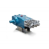
CAT piston pump 281
$4000.00 -

Droichead Zirconia Plu
$10.00 -

E.max crown, Veneer, I
Inquiry -
ReSiC Beams/plates/bur
$16.00 -
RSiC Slabs Boards Tile
$15.00 -
RSiC Batts as Kiln she
$15.00 -

RSiC Tube by recrystal
$10.00 -
RSiC Kiln Furniture (B
$16.00 -
RSiC Burner Nozzle Fla
$18.00 -
RSiC Beam Support Pill
$16.00 -

RSiC plate Slab Board
$15.00 -

NSiC Tube Pipes by Nit
Inquiry -
used excavator hudraul
$16600.00 -
NSiC Thermocouple Prot
Inquiry -

Stalk Riser Tube for L
Inquiry -
NSiC Ceramic Heater Pr
Inquiry -

RSiC NSiC Ceramic Kiln
Inquiry -
used excavator hudraul
$11500.00
Product parameters
closure
This shop is operated by agent
- Set up shop
- Authorized by Manufacturers & Suppliers online marketplace B2B platform GongWong.com, can provide agency service
- Service Introduction
- Authorized product, Internet cloud promotion service integrating certification promotion and procurement inquiry
- Intelligent website construction
- PC terminal + mobile terminal, create a cost-effective corporate website!
closure