1/5

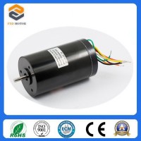
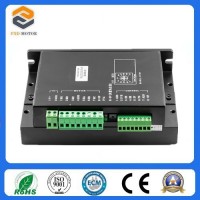
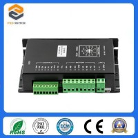
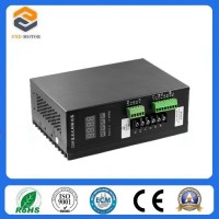
24V-48V Brushless Motor Driver with Ce Certification (BLMD-02)
$62.00 / Piece
- FOB Price:
- Negotiable | Get Latest Price
- Order Quantity:
- 1 Set / Sets
- Supply Ability:
- 1000 Set / Sets per Month
- Port:
- shanghai
- Payment Terms:
- T/T L/C D/P D/A Credit Card PayPal Cash Escrow Other
- Delivery Detail:
- 5 days
Hot in store
-
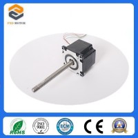
2 Phase NEMA23 Linear Stepping Motor wit
$35.50 -
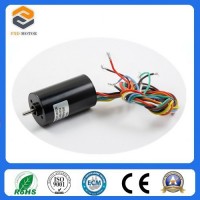
35mm BLDC Coreless Motor for Car Motors
$95.00 -
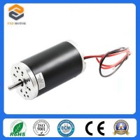
22mm BLDC Coreless Motor for Aeromodel
$80.00 -
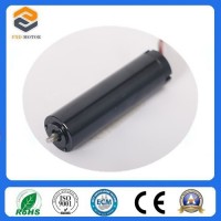
16mm Coreless Brushless DC Motor for Tin
$80.00 -
BLDC Coreless Motor for Medical Device (
$100.00 -
24V-48V Brushless Motor Driver with Ce C
$62.00 -
3 Phase Brushless Motor Controller (BLMD
$62.00 -
Made in China Electric DC Brushless Moto
$62.00
Product Details
Product Name: 24V-48V Brushless Motor Driver with Ce Certification (BLMD-02) Model NO.: BLMD-02 Material: Aluminum Alloy Customized: Customized Condition: New Certification: RoHS, CCC, ISO: 9001, SGS, CE Function: Automatic Control Signal: Continuous Mathematical Model: Non-Linear Structure: Combination Task: Control Power Input Type: DC Vlotage 24V-48V Output Current: 15A Price: Negotiable and Competitive Price Trademark: fxd motors Transport Package: Form Box and Carton Specification: CE, ROHS Origin: Changzhou City Jiangsu Province China HS Code: 8501310000 Product Description This closed loop speed control controller with latest IGBT and MOS Power devices controls closed loop speed by brushless dc motor's hall signal. PID speed regulator is set in control link. Reliable control system, especially always achieve the maximum total torque at low speed. The speed control range is from 150 to 10000rpm1. Characteristics1PID speed and current bicyclical regulator2High performance and low price320KHZ chopping frequency4The electrical braking function makes motor with quick response5The overload factor is higher than 2 and always can achieve the maximum total torque at low speed6With Fault alarm function like overvoltage, under voltage, over current, over temperature, the Hall signal illegal etc7Compatible withno hall driver, can be used as brushless no hall driver2. Electrical Specifications1Standard input voltage24VDC-48VDC,lowest voltage 12V, maximum voltage 70VDC2Maximum input overload protection current30 A3Continuous output current15 A4Acceleration time constant(default value)0.2 s5Stall protection time5 s, the other can be customizedSafety PrecautionsThis product belongs to the professional electrical equipment, should by professional and technical personnel for installation, commissioning, operation and maintenance. Improper use will cause electric shock, fire or explosion hazard. This product is a DC power supply; make sure that the positive and negative power supply is correct. Do not plug and connect cables when the power is on. And there is no electricity short of cable otherwise will lead to damage of product. If you want to change direction of running motor, the motor must be slowed down to stop and then reversing.The controller is unsealed; do not mix with screws, metal shavings and other conductive matter or combustible matter. Please note to avoid moisture and dust during storage and use. The controller is power equipment; try to keep the cooling ventilation.Guarantee restrictionsFuxianda products warranty scope is limited to products' devices and processes (i.e. consistency). Fuxianda Electromechanical does not guarantee that the products can suitable for customers' specific use because whether is suitable for also related to technical requirements, using conditions and environment. We do not recommend this product for clinical useTerminal Interface DescriptionIpower inputLead angle No.Lead angle nameChinese definitions1V+DC input+24-48 VDC2GNDGND inputII. Motor input Lead angle No.Lead angle nameChinese definitions1MAMotor phase A2MBMotor phase B3MCMotor phase C4GNDGND5HAHall signal phase A input terminal6HBHall signal phase B input terminal7HCHall signal phase C input terminal8+5VHall signal power lineIII Control signal section1GNDsignal ground2F/RPositive and reverse control: reversal with GND, forward without it. When reversing switch, you should turn off EN3ENEnable control: motor runs with EN ground connection (online), motor does not run when EN is not connected (offline)4BKBrake control: Normal work without ground connection, electric motor brake with ground connection, when the load inertia is large, it should use pulse signal mode, adjust the pulse width to control the magnitude of the braking effect.5SVAnalog voltage input terminal: Attenuate from 0 to 100%, when the external speed command connect 0 ~ 5V it can adjust speed and test machine.6PGMotor speed pulse output: when the number of pole pairs is P, 6P output pulses per revolution (OC gate input)7ALMAlarm output: when the circuit is in an alarm state, with low output (OC gate output)8+5VSpeed voltage output: use potentiometer formed continuously adjustable in SV and GND.9Built-in potentiometerAdjust motor speed, can adjust from 0 to 100%Wiring Diagram of controller &brushless motor3. Mechanical installation4.Function and UseSpeed adjustment modeThe drive offers two speed control mode users can choose one:I Internal potentiometer speed adjustment: Make counterclockwise rotation of potentiometer in drive panel, motor speed decreases. The speed increases in clockwise rotation. Potentiometer must be set at a minimum when the user uses the external input state governorII External input speed adjustment connects the two fixed end of external potentiometer to GND &+5V terminal. Use external potentiometer (5K-100K) to adjust speed by connecting adjustment terminal to SV terminal. Speed can also be achieved by inputting analog voltage to SV ends (relative to GND) from control units (e.g. PLC, SCM, etc.) SV terminal acceptable range of DC OV ~ + 5V, corresponding to the motor speed from 0 to rated speed.III You can also use an external digital signal to adjust speed. Add Pulse width digital signal (PWM) with +5V amplitude and 1 KHz ~ 2 KHz frequency between SV and GND to adjust speed. Motor speed adjusted by linear duty cycle. Then you can adjust the potentiometer R-SV SV digital signal amplitude values of 0 to 1.0 ratio attenuation process, generally adjusted to 1.0 R-SV, the SV input digital signal attenuation process do.Mtor run / stop control (EN)By controlling the relative GND terminal EN passes, off to control the operation of the motor and stop. When the terminal is disconnected, the motor runs and vice versa motor stops. Use the run / stop control to stop the motor end, the motor is a natural park, which related to the movement of the load inertia.Motor forward / reverse control (F / R)By control the terminals F / R and GND to control the direction of rotation. When the F / R with the terminal GND is not activated, the motor runs clockwise (facing the motor shaft), whereas the motor to turn counterclockwise. To avoid damage to the drive motor rotation change should be the motor stops after exercise. Steering operation is changed again, to avoid running direction of the operation with the motor running.Braking (BREAK)Control motor braking stop by controlling the BK terminal and GND terminal turned on and off. When the control terminal and the terminal GND BK disconnected, the motor is running, the motor is turned on fast braking to stop, break shut down faster than the natural specific downtime and load inertia related to the user's system. Braking downtime has impact on both electrical and machine, if no special stop requirement should naturally stop.Motor output speed signal (PG)Speed pulse output, the port is OC output (30V / 10mA max) To get the signal should be on the power of indirect 3KΩ ~ 10KΩ pull-up resistor. The end poles with fixed pulse width output frequency is proportional to motor speed (50uS) negative pulse train outputs the number of pulses per revolution of the motor 3 x N, N of the motor. Example: two pairs of poles that is four-pole motor 12 pulses per revolution. When the motor speed is 500 rev / time, the sharing terminal PG output pulse is 6000.Alarm OutputDrive alarm output, the port is OC output (30V / 10mA max). To get the signal should be on the power of indirect 3KΩ ~ 10KΩ pull-up resistor. The terminal conduct with GND terminal (low level), While the drive to stop working on their own in an alarm state.Drive failureThe controller enters into protection state when it's overvoltage or over current. The drive will automatically stop working, the motor is stopped, and the blue light on the drive is flash gravel. As long as the enable terminal is reset (i.e. EN and GND disconnected) or power is failure, the drive to disarm the alarm. Please check the motor wiring when occurring this fault.5.Controller using stepI Correctly connect the motor line, the Hall line and power line. Incorrect wiring can cause damage to the motor and driveII When use the built-in potentiometer to adjust speed, connect EN terminal to GND terminal and SV terminal with +5V. Adjust speed with built-in potentiometer R-SVIII If use external potentiometer, make the R-SV transferred to a position 1.0. At the same time connect external potentiometer fixed point (intermediate interface) to controller SV terminal. Connect another two to GND and +5V terminal.V Operate with power the motor in a state of closed-loop top speed. Adjust fader potentiometer to the desired speed
Contact with Supplier
Recommend product
-
Stripped Soft Goose Fe
$3.00 -
plastic ball grinding
$30000.00 -
CAT piston pump 281
$4000.00 -

Droichead Zirconia Plu
$10.00 -

E.max crown, Veneer, I
Inquiry -
ReSiC Beams/plates/bur
$16.00 -
RSiC Slabs Boards Tile
$15.00 -
RSiC Batts as Kiln she
$15.00 -

RSiC Tube by recrystal
$10.00 -
RSiC Kiln Furniture (B
$16.00 -

RSiC Burner Nozzle Fla
$18.00 -
RSiC Beam Support Pill
$16.00 -
RSiC plate Slab Board
$15.00 -

NSiC Tube Pipes by Nit
Inquiry -
used excavator hudraul
$16600.00 -

NSiC Thermocouple Prot
Inquiry -

Stalk Riser Tube for L
Inquiry -
NSiC Ceramic Heater Pr
Inquiry -

RSiC NSiC Ceramic Kiln
Inquiry -
used excavator hudraul
$11500.00
Product parameters
closure
This shop is operated by agent
- Set up shop
- Authorized by Manufacturers & Suppliers online marketplace B2B platform GongWong.com, can provide agency service
- Service Introduction
- Authorized product, Internet cloud promotion service integrating certification promotion and procurement inquiry
- Intelligent website construction
- PC terminal + mobile terminal, create a cost-effective corporate website!
closure