1/5


0.87 INCH OLED DISPLAY
$0.00 / PCS
1PCS (MOQ)
- FOB Price:
- Negotiable | Get Latest Price
- Order Quantity:
- 1 Set / Sets
- Supply Ability:
- 1000 Set / Sets per Month
- Port:
- shanghai
- Payment Terms:
- T/T L/C D/P D/A Credit Card PayPal Cash Escrow Other
- Delivery Detail:
- 5 days
Hot in store
-
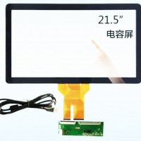
21.5 inch capacitive touch screen with U
$65.00 -
0.87 INCH OLED DISPLAY
Inquiry -

16x2 Character LCD Display
$4.00 -

122x 32 Graphic LCD Display
$5.00 -

1602 character LCD Display
$3.00 -

0.66inch PM OLED Monochrome White 64*48
Inquiry -

3.5-inch 320*480 CHIMEI TFT for Smart re
$6.80 -

3.5inch 320*240 Chimeiglass, HX8238D wit
$8.50
Product Details
Product Description

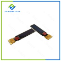
Product instruction of the 0.87 inch OLED Display
We supply 0.87 inch OLED Display which is the graphic OLED display panel made of 128x32 individual white OLED pixels,diagonal is only 0.87 inch.The controller ic SSD1316, communicates via I2C serial interface.
Product Specification of the 0.87 inch OLED Display
|
Item
|
Dimension
|
Unit
|
|
Dot Matrix
|
128x32 Dots
|
?
|
|
Module dimension
|
29.0x8.7x1.21
|
mm
|
|
Active Area
|
21.356x5.324
|
mm
|
|
Pixel Size
|
0.147x0.147
|
mm
|
|
Pixel Pitch
|
0.167x0.167
|
mm
|
|
Display Mode
|
Passive Matrix
|
|
|
Display
|
Color White
|
|
|
Drive Duty
|
1/32 Duty
|
|
|
IC
|
SSD1306
|
|
|
Interface
|
I2C
|
|
|
Size
|
0.87 inch
|
|
Product Drawing of the 0.87 inch OLED Display
Product Interface Pin Function of the 0.87 inch OLED Display
|
No.
|
Symbol
|
Function
|
|
1
|
C2P
|
Positive Terminal of the Flying Inverting Capacitor Negative Terminal of the Flying Boost Capacitor The charge-pump capacitors are required between the terminals. They must be floated when the converter is not used.
|
|
2
|
C2N
|
|
|
3
|
C1P
|
|
|
4
|
C1N
|
|
|
5
|
VDDB
|
Power Supply for DC/DC Converter Circuit This is the power supply pin for the internal buffer of the DC/DC voltage converter. It must be connected to external source when the converter is used. It should be connected to VDD when the converter is not used.
|
|
6
|
NC
|
Not Connected.
|
|
7
|
VSS
|
Ground of Logic Circuit This is a ground pin. It acts as a reference for the logic pins. It must be connected to external ground.
|
|
8
|
VDD
|
Power Supply for Logic This is a voltage supply pin. It must be connected to external source.
|
|
9
|
RES#
|
Power Reset for Controller and Driver This pin is reset signal input. When the pin is low, initialization of the chip is executed.
|
|
10
|
SCL
|
When serial mode is selected, D1 will be the serial data input SDA and D0 will be the serial clock input SCL.
|
|
11
|
SDA
|
|
|
12
|
IREF
|
Current Reference for Brightness Adjustment This pin is segment current reference pin. A resistor should be connected between this pin and VSS. Set the current lower than 10μA.
|
|
13
|
VCOMH
|
Voltage Output High Level for COM Signal This pin is the input pin for the voltage output high level for COM signals. A capacitor should be connected between this pin and VSS.
|
|
14
|
VCC
|
Power Supply for OEL Panel This is the most positive voltage supply pin of the chip. A stabilization capacitor should be connected between this pin and VSS when the converter is used. It must be connected to external source when the converter is not used.
|
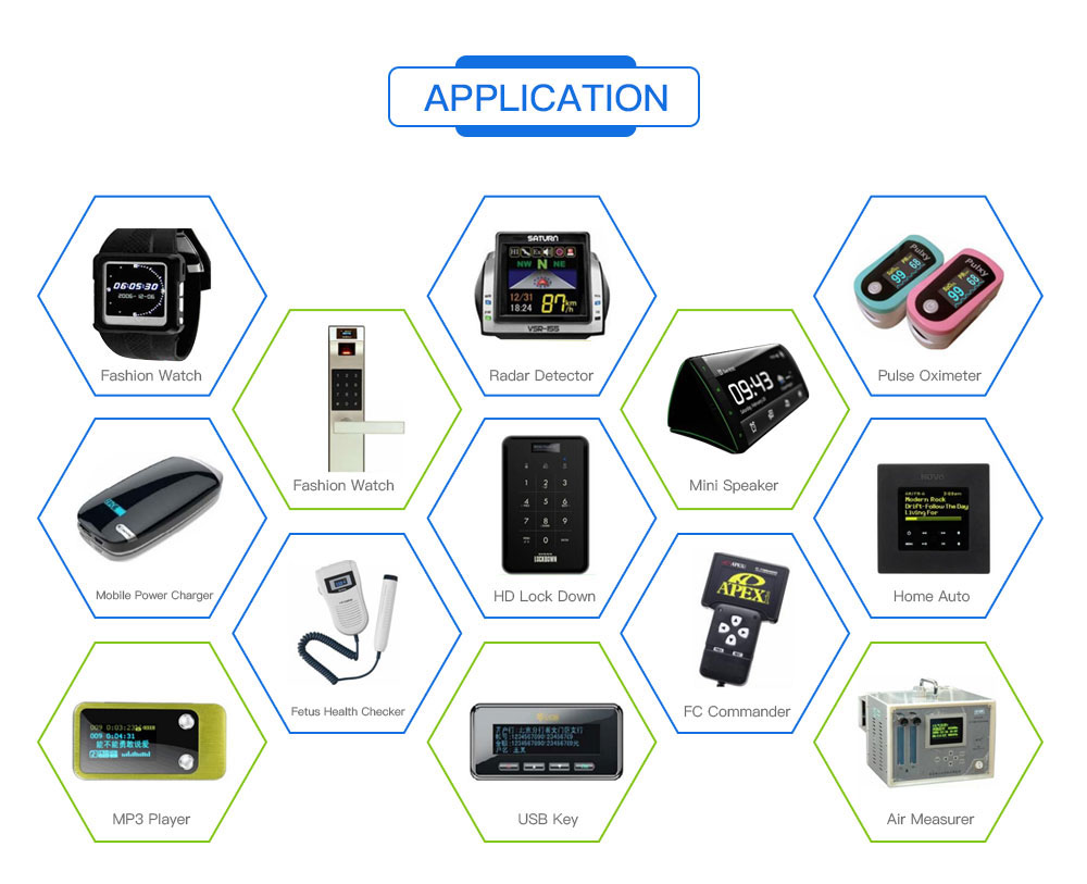
Product Feature and Application of the 0.87 inch OLED Display
Due to the controller's built-in voltage generation,only a single 3.3V power supply is needed. Because the display makes its own light, no backlight is required. This reduces the power required to run the OLED and is why the display has such high contrast,extremely wide viewing angle and extremely operating temperature.The fpc is the soldering type,no need connector.Just solder the FPC on your PCB directly.
It's easily controlled by MCU such as 8051,PIC,AVR,ARDUINO,ARM and Raspberry Pi.It can be used in any embedded systems,industrial device,security,medical and hand-held device.
Product OLED Lifetime of the 0.87 inch OLED Display
|
ITEM
|
Conditions
|
Min
|
Typ
|
Remark
|
|
Operating Life Time
|
Ta=25? / Initial 50% check board brightness Typical Value
|
20,000 Hrs
|
?
|
Note
|
Notes:
1. Life time is defined the amount of time when the luminance has decayed to <50% of the initial value.
2. This analysis method uses life data obtained under accelerated conditions to extrapolate an estimated probability density function (pdf) for the product under normal use conditions.
3. Screen saving mode will extend OLED lifetime.
Product Quality Control of the 0.87 inch OLED Display
Before package and shipment, the original products will be tested one by one by our technicians and QC team to make sure the quality of every product is good.
We will test goods strictly according to our standard inspection before shipment.
Delivery, shipping and Severing of the 0.87 inch OLED Display
1) .Payment Terms: T/T, Western Union.
2). Shipping: prompt delivery by UPS, EMS, DHL, TNT, FedEx, or by air.
3). Delivery time: 3 days for goods in stock, 3-4 weeks for mass production goods.
4). Packaging Details: Packed in anti-static bags with foam box to ensure safety in transportation.
5). Delivery Details: 1 to 30 days. The delivery fee is up to the weight and volume of the products.
6). Samples: Our company offers samples for quality test or other business purposes, but we kindly ask you to pay for samples and the freight.
FAQ
Q: What is the MOQ?
A: Generally if you choose the different products, our MOQ also will be different.
A: Generally if you choose the different products, our MOQ also will be different.
Q: What about the delivery time?
A: The LCD products need 3-4 weeks to be made after receive deposit.
A: The LCD products need 3-4 weeks to be made after receive deposit.
Q: Does your product have any warranty?
A: Yes, we offer 12 months warranty for our products. Damage due to misuse, ill treatment and unauthorized modifications and repairs are not covered by our warranty.
A: Yes, we offer 12 months warranty for our products. Damage due to misuse, ill treatment and unauthorized modifications and repairs are not covered by our warranty.
Q: What's your payment method?
A: We usually accept the payment methods include T/T, Western Union. 50-100% deposit in advance and balance before shipping upon the payment amount. Buyer can choose which payment ways that you accept.
A: We usually accept the payment methods include T/T, Western Union. 50-100% deposit in advance and balance before shipping upon the payment amount. Buyer can choose which payment ways that you accept.
Q: What's your shipping method?
A: We provide comprehensive shipping methods.
For small quantity orders we ship by UPS Air-Express,or DHL/FEDEX/TNT/EMS Express service, it is safe and fast.
For large quantity orders we ship by buyer's cargo agent in China, we can also ship by Air transportation or sea transportation.
For large quantity orders we ship by buyer's cargo agent in China, we can also ship by Air transportation or sea transportation.
Q: Do you offer custom solution?
A: Yes, we can offer custom solution if standard products couldn't meet buyer' requirements.
A: Yes, we can offer custom solution if standard products couldn't meet buyer' requirements.
Latest News
Recommendations
Hot Tags: 0.87 inch OLED Display, China, Manufacturers, Suppliers, Factory, Made in China, Customized, In stock, Bulk, Quotation, High quality
Send Inquiry
Please Feel free to give your inquiry in the form below. We will reply you in 24 hours.
Contact with Supplier
Recommend product
-
Stripped Soft Goose Fe
$3.00 -
plastic ball grinding
$30000.00 -
CAT piston pump 281
$4000.00 -
Droichead Zirconia Plu
$10.00 -
E.max crown, Veneer, I
Inquiry -
ReSiC Beams/plates/bur
$16.00 -
RSiC Slabs Boards Tile
$15.00 -
RSiC Batts as Kiln she
$15.00 -

RSiC Tube by recrystal
$10.00 -
RSiC Kiln Furniture (B
$16.00 -
RSiC Burner Nozzle Fla
$18.00 -
RSiC Beam Support Pill
$16.00 -
RSiC plate Slab Board
$15.00 -

NSiC Tube Pipes by Nit
Inquiry -
used excavator hudraul
$16600.00 -
NSiC Thermocouple Prot
Inquiry -

Stalk Riser Tube for L
Inquiry -
NSiC Ceramic Heater Pr
Inquiry -

RSiC NSiC Ceramic Kiln
Inquiry -
used excavator hudraul
$11500.00
Product parameters
closure
This shop is operated by agent
- Set up shop
- Authorized by Manufacturers & Suppliers online marketplace B2B platform GongWong.com, can provide agency service
- Service Introduction
- Authorized product, Internet cloud promotion service integrating certification promotion and procurement inquiry
- Intelligent website construction
- PC terminal + mobile terminal, create a cost-effective corporate website!
closure