1/5

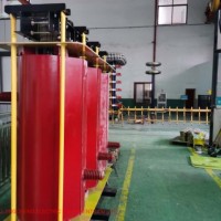
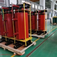
Pole Mounted Reactive Power Compensation Device
$0.00
- FOB Price:
- Negotiable | Get Latest Price
- Order Quantity:
- 1 Set / Sets
- Supply Ability:
- 1000 Set / Sets per Month
- Port:
- shanghai
- Payment Terms:
- T/T L/C D/P D/A Credit Card PayPal Cash Escrow Other
- Delivery Detail:
- 5 days
Hot in store
-
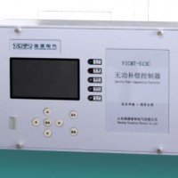
Power Factor Controller
$350.00 -
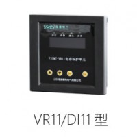
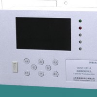
Microcomputer Protection Unit
$350.00 -
High-Voltage Reactive Powercompensation
$350.00 -
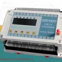
Controller of Capacitor Bank
$350.00 -
35kv Series Reactor
Inquiry -
35kv Series Epoxy Cast Dry Core Reactor
Inquiry -
35kv Shunt Capacitor Bank
Inquiry -
High Voltage Shunt Capacitor
Inquiry
Product Details
Product Name: Pole Mounted Reactive Power Compensation Device Model NO.: TBBZ10-1200 Filter: Paper Capacitor Tuning: Polystyrene Capacitor Electrolyte: Inorganic Medium Manufacturing Material: Polypropylene Structure: Fixed Capacitor Capacitance: 50-100uf Packaging Type: Surface Mount Application: General Purpose, AC / Motor, Power, High Voltage Type: Polystyrene-film-capacitors Trademark: Jingcheng electric Transport Package: Wooden Book Specification: copper or aluminum Origin: China HS Code: 8532909000 Product Description Technical parameters of pole mounted reactive power compensation device1 OverviewTBBZcolumn type automatic switching high voltage shunt capacitor device (hereinafter referred to as the device) is suitable for 10kV or 6kV distribution line, which is used to improve power factor, reduce line loss and improve voltage quality.The device can be set by the user according to the needs of the line to realize the automatic switching of the shunt capacitor. At the same time, it also has the protection functions of short circuit, over-current, over-voltage and under voltage. The JCZ5 series vacuum contactor adopted has the characteristics of no bounce when closing, no re ignition when opening and long service life; high voltage shunt capacitor with internal fuse and discharge resistance; automatic controller for reactive power compensation has strong anti-interference ability and reliable performance; the device is also equipped with outdoor control power transformer. The device has compact structure and convenient installation.2. Environmental conditions for use2.1 ambient air temperature: upper limit + 45 ºC, lower limit - 40 ºC.2.2 altitude: no more than 1000m.2.3 wind speed: no more than 35m / s.2.4 sunshine: the amplitude (maximum) is 0.1w/cm2.2.5 earthquake: the seismic intensity shall not exceed 8 degrees.2.6 chemical conditions: the installation site is free of harmful gases and vapors, and there is no conductive or explosive dust.3 model meaning and main technical parameters1 Shunt capacitor TBBZ11 - 300 - 3W 12 Arrester 5wr-17 / 4533 Open type current transformer 4 power transformer DC-2 / 10 1 set5 pole voltage and reactive power controller 1 set6 GPRS communication module 1 set of GPRS7vacuum contactor JCZ5-12d / 400A8 protection current transformer 2 sets9 cabinet body (stainless steel plastic spraying) 1 side10 busbar (with color code) TMY 4 × 40 1 set11 composite casing (through wall casing) ZW8-630 3 pieces12 indicator light, micro break and other secondary components 1 set4 structure and working principle4.1 the device consists of full film high voltage shunt capacitor (with discharge resistance and internal fuse), vacuum contactor, voltage transformer, zinc oxide arrester and current transformerSensor, discharge coil, high voltage reactive power compensation controller, protection circuit and hardware.4.2 the device has two types of structure: double pole installation and single pole installation. See attached figure for primary wiring.4.3 working principle4.3.1 the high voltage power supply of the device is connected, and the voltage transformer provides power supply to the automatic controller of high voltage reactive power compensation (hereinafter referred to as the automatic controller) and the operating mechanism of vacuum contactorCurrent 100V power supply. When the voltage, power factor or operation time of the line is within the preset switching range, the automatic controller will connect the power supply of the operating mechanism to close the vacuum contactor and put the capacitor bank into the line operation. When the voltage, power factor or operation time of the line is in the cut-off range, the automatic controller will turn on the power supply of the shunt release to open the vacuum contactor and exit the operation of the capacitor bank. Thus the automatic switching of capacitor is realized, the purpose of improving power factor, reducing line loss and improving voltage quality is achieved, and reactive power reverse transmission is prevented at the same time.4.3.2When the line voltage is higher than the setting value of overvoltage protection (1.1 ~ 1.3un), the automatic controller will delay 30s to trip the vacuum contactor and the capacitor will be out of operation.Within the delay time, the line voltage returns to normal and the switch does not trip. After the switch trips, when the line voltage returns to normal, the automatic controller delays for 10 minutes to close the switch.
Contact with Supplier
Recommend product
-
Stripped Soft Goose Fe
$3.00 -
plastic ball grinding
$30000.00 -
CAT piston pump 281
$4000.00 -

Droichead Zirconia Plu
$10.00 -

E.max crown, Veneer, I
Inquiry -
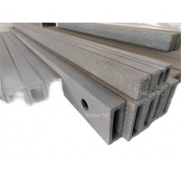
ReSiC Beams/plates/bur
$16.00 -
RSiC Slabs Boards Tile
$15.00 -
RSiC Batts as Kiln she
$15.00 -

RSiC Tube by recrystal
$10.00 -
RSiC Kiln Furniture (B
$16.00 -
RSiC Burner Nozzle Fla
$18.00 -
RSiC Beam Support Pill
$16.00 -
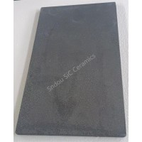
RSiC plate Slab Board
$15.00 -

NSiC Tube Pipes by Nit
Inquiry -
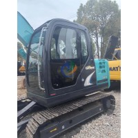
used excavator hudraul
$16600.00 -
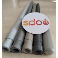
NSiC Thermocouple Prot
Inquiry -

Stalk Riser Tube for L
Inquiry -
NSiC Ceramic Heater Pr
Inquiry -

RSiC NSiC Ceramic Kiln
Inquiry -
used excavator hudraul
$11500.00
Product parameters
closure
This shop is operated by agent
- Set up shop
- Authorized by Manufacturers & Suppliers online marketplace B2B platform GongWong.com, can provide agency service
- Service Introduction
- Authorized product, Internet cloud promotion service integrating certification promotion and procurement inquiry
- Intelligent website construction
- PC terminal + mobile terminal, create a cost-effective corporate website!
closure